Home

Horn consensus Alternative d flip flop transition table Joseph Banks point adopt

flip-flop-excitation-table | Sequential Logic Circuits || Electronics  Tutorial
flip-flop-excitation-table | Sequential Logic Circuits || Electronics Tutorial

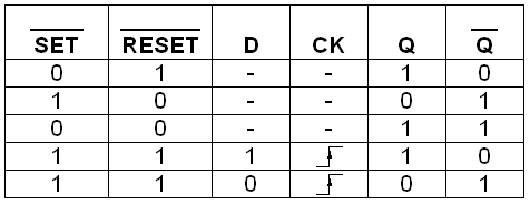
Digital Flip-Flops - SR, D, JK and T Flip-Flops - Sequential Logic Circuits

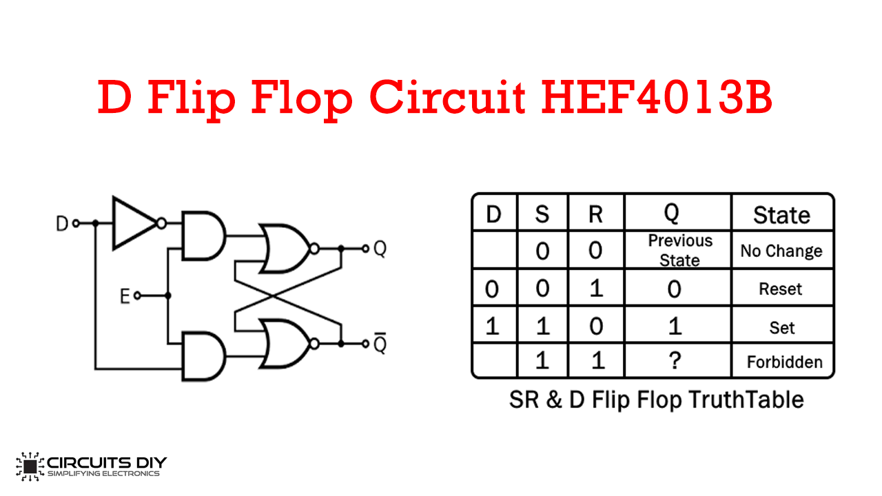
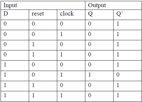
D Flip Flop Circuit using HEF4013B - Truth Table

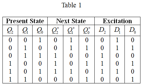
Solved: Derive the state transition table and D flip-flop input eq... |  Chegg.com
Solved: Derive the state transition table and D flip-flop input eq... | Chegg.com

Flip-flop circuits
Flip-flop circuits

Introduction to D flip flop - YouTube

Flip-flop Types, Logic symbols, Truth Table & Applications - study notes

D Flip-Flop Explained | Truth Table and Excitation Table of D Flip-Flop -  YouTube
D Flip-Flop Explained | Truth Table and Excitation Table of D Flip-Flop - YouTube

JK Flip Flop: What is it? (Truth Table & Timing Diagram) | Electrical4U

Truth Table of SR-Flip Flop Using NOR and NAND Gates Configurations |  Download Scientific Diagram
Truth Table of SR-Flip Flop Using NOR and NAND Gates Configurations | Download Scientific Diagram

How to Build a D Flip Flop Circuit with a 4013 Chip

Virtual Labs
Virtual Labs

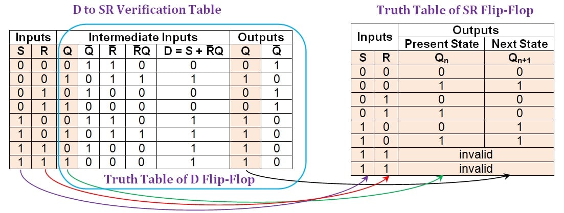
Conversion of D Flip-Flops - Technical Articles

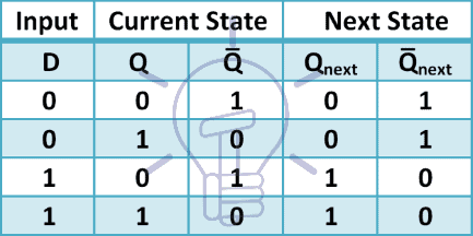
Transition Tables D-Flip-Flop Transition Table D-Flip-Flop the Present and  the Next States of the Outputs Are Indicated the Arrows Indicate After the  Clocking Edge Present NextInput 0→0 0-1 1→1 the Input Is
Transition Tables D-Flip-Flop Transition Table D-Flip-Flop the Present and the Next States of the Outputs Are Indicated the Arrows Indicate After the Clocking Edge Present NextInput 0→0 0-1 1→1 the Input Is

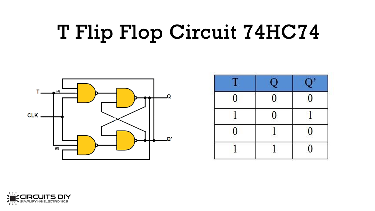
T Flip-Flop Circuit using 74HC74 - Truth Table and Working

Solved Consider a FSM with the following State Transition | Chegg.com

JK Flip Flop and SR Flip Flop - GeeksforGeeks

Conversion of S-R Flip-Flop into D Flip-Flop - GeeksforGeeks

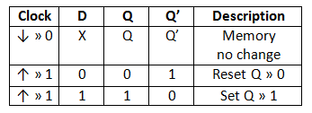
D Flip-Flop - Flip-Flops - Basics Electronics

What is excitation table? List the excitation table for SR-FF, JK-FF D-FF  and T-FF. | Suresh KUMAR Mukhiya
What is excitation table? List the excitation table for SR-FF, JK-FF D-FF and T-FF. | Suresh KUMAR Mukhiya

D Flip Flop in Digital Electronics - Javatpoint

Conversion of D Flip-Flops - Technical Articles

Realization of negative edge triggered D flip flop by proposed RDFF... |  Download Scientific Diagram
Realization of negative edge triggered D flip flop by proposed RDFF... | Download Scientific Diagram

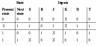
circuit analysis - Design a 4-bit binary counter using D flip-flop -  Electrical Engineering Stack Exchange
circuit analysis - Design a 4-bit binary counter using D flip-flop - Electrical Engineering Stack Exchange

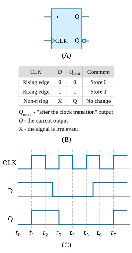
D Flip Flop (D Latch): What is it? (Truth Table & Timing Diagram) |  Electrical4U
D Flip Flop (D Latch): What is it? (Truth Table & Timing Diagram) | Electrical4U

Conversion of D Flip-Flops - Technical Articles